
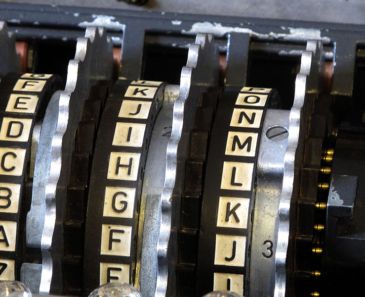
Rotors with Alphabet Rings
One of the projects I have been working on with VirPack has been the establishment of a developer’s training program and central to that program has been Robert Martin’s materials on Clean Code. Â While many of Martin’s ideas have sparked some interesting discussions at VirPack, none has been more controversial than his discussion of Test Driven Development. Â Martin holds to a three-part cycle: Fail, Pass, Re-factor – in which you write just enough of a test to fail, just enough code to pass, and sometimes re-factor to clean up before cycling back to failure. Â This results in a number of areas, particularly in Martin’s examples, where tests seem to be written merely to justify an action everyone agreed was necessary in the first place — say, a test to see if you can construct an object which is then run, and fails, because the object does not yet exist.
While I am pretty well sold on Martin’s coding philosophy I decided to take my coworkers objections under advisement but with a grain of salt. Â Most of the Kata and examples that Martin works through are very simple; they have to be in order to be short enough and accessible enough to communicate the points he is trying to make about software development but that simplicity also means that the early fixed-costs of TDD seem very big compared to the actual “meat” of the problem he is trying to solve.
So I set out to try out true TDD on a project which I knew was going to be complicated. Â Martin’s examples of things like a bowling score calculator had just a few plausible test cases and a mere handful of interesting results which could emerge from a complete examination of all possible execution paths. Â I wanted something much bigger and much more complicated and the historian in me knew just where to look.
Enigma
From September of 1939 to the summer of 1941 German wolfpacks prowled the depths of the North Atlantic and sent millions of tons of Allied shipping to the ocean floor. Â The effectiveness of the German submarine warfare program was based in large part upon the Nazi government’s ability to communicate with their ships in secret via the use of wheel-based cypher system called Enigma. Â Enigma machines turned a message – say – “CONVOYAPPROACHINGDOVER” into an unintelligible string of nonsense: “QIOYABCWUXLSQXZEJMERYQ.”
The Enigma machine did this job very well.  Early enigma machines had slots of three rotors and a single, fixed, reflector.  Each keypress sent a signal form the keyboard, and through each rotor where it would be swapped with another letter.  Then the signal would hit a reflector which would transform the letter a fourth time  before routing it back through the rotors a second time.  So, for example, the encryption of the letter “A” might look like this where rotor positions are noted as [R1], [R2], [R3] and the reflector is indicated by [R]:
[R1]A->B, [R2]B->J, [R3] J->Z, [R] Z->T, [R3]: T->L, [R2] L->K, [R1] K->U
And so hitting the “A” key would cause the letter “U” to light up, indicating that the machine had cyphered the letter A to the letter U. Â But hit “A” again and you’d get a different letter because the rotor in position 1 would advance; as a result pressing “A” would start the chain at the “B” contact of the rotor in position 1 and the letter produced by the position 1 rotor would be offset by one position as it entered the position 2 rotor, giving us this chain where “A” maps to “B.” Â Again, we I’ll use [R1], [R2], and [R3] to indicate character remappings through a rotor and [R] to indicate the reflector but we will also see [O1] indicating a transformation caused by the relative offset of the rotor in position 1 from the keyboard and the rotor in position 2.
[O1] A->B, [R1] B->D, [O1] D->C, [R2] C->D, [R3] D->F, [R]Â F->S, [R3] S->S, [R2] S->E, [O1] E->F, [R1] F->C, [O1] C->B
Obviously this gets complicated very quickly. Â Since output depends on a plug board, three (or more) rotor positions, the order of the rotors, the reflector, and internal rotor ring-settings we’re looking at a fairly daunting problem. Â Incidentally, that’s probably how a handful of British and Polish mathematicians felt in the late 1930s.
Enigma as a Kata
In Robert Martin’s bowling kata we see that test driven development can sometimes lead us to a solution which is much less complicated than we might first have assumed. Â Most of the objects we might think necessary for a proper implementation of a bowling score keeper — frames, rolls, etc — are unnecessary when we boil bowling scores down to their essence. Â This is, unfortunately, not true of Enigma. Â Because it is a crytographic system, Enigma output is enormously complicated and presents no emergent pattern to the developer — indeed it was engineered not to do so. Â To create an Enigma emulator using TDD therefore, we must break the Enigma down into its component parts and build each of them individually. Â TDD can then be applied to the final system as a whole but, by that time, the bulk of the complex encryption work is done.
A simple Enigma consists of the following components
Plugboard
The plugboard swaps pairs of characters. Â The entire alphabet could be swapped around in this way but generally exactly 10 plugs were used. Â To illustrate, imagine that for a given setting of the rest of the Enigma machine the letter A->R, B->Z. Â If the plugboard wired B->A then the output for that same setting would change to: B->R, A->Z. Â The transformation happens on output too such that if we then wired Z->Q (so two pairs are wired) the outputs would be: B->R, A->Q. Â The plugboard only alters the crypt-sequence on its way to and from the rotor assembly; it does not alter the way the rotors interact with each other.
Rotors
Each rotor takes an input character and maps it to an output character. Â It can do this in two directions so that if A->B in one direction B->A in the other. Rotors have an offset which determines which of their contacts are in which position. Â If the rotor is in the “A” position then its inputs line up alphabetically: the “A” contact receives input in the “A” position, B in B and so on. Â If the rotor is in the “B” position then the “B” contact receives input in the “A” position, “C” in “B” and so on. Â Similar offsets apply to output as well. Â In the case of the rotor designated “IV” the character “B” maps to “S.” Â If Rotor IV is in its “B” position then providing it with an input of “A” will result in a signal starting at the “B” contact and emerging at the “S” contact which occupies the “R” position.
Rotors also have a “notch” or “turnover” value. Â When the rotor is in its “notch” position it allows the rotor to its left to advance.
Reflector
Reflectors are a special kind of rotor. Â In early Enigma systems they were stationary but in all cases the reflector’s transformation was one that was a mirror image of itself. Â In other words, if A->B in a given reflector then B->A. Â This was the heart of the Enigma system — it allowed messages to be easily crypted and decrypted on the same peice of equipment. Â It also introduces a fatal flaw in Enigma: a letter can never crypt to itself.
The Enigma Machine
This is just a facade that holds the entire thing together. Â In truth you will probably find the need for at least one other facade but the machine is the obvious one. Â Our machine will need to be able to crypt text, plug letter pairs, and both set and get the rotor offsets.
Interesting Test Cases
Obviously there are a lot of tests which are being left out from this list. Â Most of the get and set functions, constructors, etc are all omitted here but they should be present in your code. Â These are the tests which should tell you if the system you’ve constructed is crypting text in the way that an Enigma machine would.
Plugboard
The plugboard has the simplest tests. Â We need only check to see if transforms are happening; it’s up to the consumer of the plugboard to see that they’re happening in the right places. Â For these tests we are assuming that “A” is being swapped with “B”
- Plugs pairs translate (A->B)
- Given: ‘A’
- Expects: ‘B’
- Pluged pairs translate in reverse too
- Given: ‘B’
- Expects: ‘A’
- Non-Plugged letters translate to themselves
- Given: ‘C’
- Expects: ‘C’
Rotors
For our rotor tests we will assume that we are testing RotorI which is present on the Enigma I and all other miltiary Enigma systems issued after 1930. Â Rotor I is wired as follows “ABCDEFGHIJKLMNOPQRSTUVWXYZ” -> “EKMFLGDQVZNTOWYHXUSPAIBRCJ”. Â In most cases, when a rotor’s wiring is being discussed, only the second part of that mapping is specified; we assume that the mapping is positional to the Alphabet.
- Mapping with an offset of zero (position “A”)
- Given: ‘A’
- Expects: ‘E’
- Mapping with an offset of one (position “B”)
- Given: ‘A’
- Expects: ‘J’
- Reverse Mapping with offset of zero
- Given: ‘E’
- Expects: ‘A’
- Reverse Mapping with offset of one
- Given: ‘K’
- Expects: ‘D’
- Is In Turnover Position
- Given Offset: ‘Q’
- Expects: true (false for all other values)
Reflectors
Reflectors are just specialized rotors and your code will probably reflect that. Â Doing things that way means that the reflector has to know if it has been wired improperly.
- Invalid Wiring
- Given: “JEMZALYXVBWFCRQUONTSPIKHGD”
- Expects: ReflectorMappingException
- Valid Wiring
- Given: “EJMZALYXVBWFCRQUONTSPIKHGD”
- Note that the first character of the wiring is “E” which has an alphabetical position of 5. Â Note that the 5th character is “A” which has an alphabetical position of 1. Â If this reciprocal relationship is true for all characters in the wiring then the reflector is valid.
- Expects: No exception thrown
- Given: “EJMZALYXVBWFCRQUONTSPIKHGD”
Enigma Machine
The tests laid out here assume the following unless otherwise specified. Â The enigma machine has three rotors and one reflector. Â The rotors are, from right to left: RotorIII, RotorII, Rotor I the wirings for which are noted below.
| Rotor | Wiring | Turnover |
|---|---|---|
| RotorIII | BDFHJLCPRTXVZNYEIWGAKMUSQO | V |
| RotorII | AJDKSIRUXBLHWTMCQGZNPYFVOE | E |
| RotorI | EKMFLGDQVZNTOWYHXUSPAIBRCJ | Q |
We will also assume a fixed reflector commonly designated “Reflector B” with the following wiring: “YRUHQSLDPXNGOKMIEBFZCWVJAT” and an unwired plug-board. Â Unless otherwise specified, all tests begin with the rotors in the “AAZ” position.
- Rotors Advance On Crypt
- Given: Crypt a single character
- Expected rotor position: “AAA”
- Rotors Advance Before Crypt
- Given: “A”
- Expected: “U”
- Second Rotor Motion
- Given
- Enigma machine starting position of “AAV”
- Crypt a single character
- Expected rotor position: “ABW”
- Given
- Simple decryption/encryption test
- Given: “RBMLWDESXRUEPIWEDYLDZUKTTXGGKHLTFHKXLXFDJDMMI”
- Expected: “MAYBEINVADINGRUSSIAINTHEWINTERWASNOTAGOODIDEA”
Catches and Caveats
A TDD Kata would not be complete without an illustration of why all of this TDD work is worth your while and the Engima Kata is no exception. Â In order to make the code you have developed thus-far work properly you’re going to have to make some revisions.
Double Stepping
You will note that none of the tests provided for the Enigma Machine above require motion of the 3rd wheel. This is because the Enigma I, which these this kata has focused upon, had a bug which, in order to faithfully replicate the system, we must also implement. Â The bug is known as “double-stepping.” Â A wheel “N” can advance only if its less significant wheel “N-1” is in its notch position; for the purpose of this definition wheel zero, which does not exist, is always in its notch position. Â When wheel “N” advances, however, it carries wheel “N-1” one step forward with it so the stepping sequence for third wheel advancement should be tested as follows
- Step Prior to Doublestep Test
- Given: Starting at rotor position “ADV,” crypt one character
- Expected rotor position: “AEW”
- Doublestep Test
- Given: Starting at rotor position “AEW,” crypt one character
- Expected rotor position: “BFX”
- Step after Doublestep Test
- Given: Starting at rotor position “BFX”
- Expected rotor position: “BFY”
- Long Crypt Test Over A Doublestep
- Given
- Start Position: “ADV”
- Input: “UFSMHLYCAOFPCYDSBBVHLMNAWBXTSKANKGLZGBHIHAXIRU”
- Expected: “IHEARTHEWEATHERINARGENTINAISNICETHISTIMEOFYEAR”
- Given
Ring Settings
Each Enigma wheel has a notch position and that position is a physical characteristic of the wheel so it would be difficult to change it on the fly. Â That predictability reduced the security of the Enigma system and so the engineers who built it came up with a clever work-around. Â If the notch couldn’t be moved, perhaps the wiring inside the rotor could. Â This would have the effect of making the stepping period much harder to follow. Â The convention for this offset is called the “ring-setting” as it tells us how the outer ring of contacts corresponds to the inner letter pairings of the Enigma. Â The following tests will help you add ring-settings to your existing rotors.
- Mapping with ring-setting of 1 (position “B”) and offset of 0
- Given: “A”
- Expected: “J”
- Reverse Mapping with ring-setting of 1 (B) and offset of 0
- Given: “K”
- Expected: “A”
- Mapping with ring-setting of 6 (F) and offset of 24 (Y)
- Given: “A”
- Expected: “W”
Leave a Reply

Photos


